Vishay E Type N-Channel Power MOSFET, 35 A, 650 V Enhancement, 3-Pin TO-220AB SiHP080N60E-GE3
- RS 제품 번호:
- 228-2875
- 제조사 부품 번호:
- SiHP080N60E-GE3
- 제조업체:
- Vishay

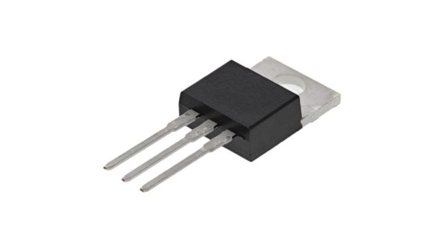
본 이미지는 참조용이오니 재확인이 필요하시면 문의해주세요.
대량 구매 할인 기용 가능
View bulk pricing optionsSubtotal (1 pack of 2 units)*
₩13,500.00
재고있음
- 추가로 2026년 7월 27일 부터 698 개 단위 배송
더 자세한 내용이 필요하신가요? 필요한 수량을 입력하고 '배송일 확인'을 클릭하면 더 많은 재고 및 배송 세부정보를 확인하실 수 있습니다.
수량 | 한팩당 | 한팩당* |
|---|---|---|
| 2 - 8 | ₩6,750.00 | ₩13,500.00 |
| 10 - 18 | ₩6,540.00 | ₩13,080.00 |
| 20 - 24 | ₩6,340.00 | ₩12,680.00 |
| 26 - 98 | ₩6,160.00 | ₩12,320.00 |
| 100 + | ₩5,970.00 | ₩11,940.00 |
* 참고 가격: 실제 구매가격과 다를 수 있습니다
- RS 제품 번호:
- 228-2875
- 제조사 부품 번호:
- SiHP080N60E-GE3
- 제조업체:
- Vishay
사양
참조 문서
제정법과 컴플라이언스
제품 세부 사항
제품 정보를 선택해 유사 제품을 찾기
모두 선택 | 제품 정보 | 값 |
|---|---|---|
| 브랜드 | Vishay | |
| Product Type | Power MOSFET | |
| Channel Type | Type N | |
| Maximum Continuous Drain Current Id | 35A | |
| Maximum Drain Source Voltage Vds | 650V | |
| Package Type | TO-220AB | |
| Series | E | |
| Mount Type | Through Hole | |
| Pin Count | 3 | |
| Maximum Drain Source Resistance Rds | 80mΩ | |
| Channel Mode | Enhancement | |
| Minimum Operating Temperature | -55°C | |
| Typical Gate Charge Qg @ Vgs | 42nC | |
| Maximum Power Dissipation Pd | 227W | |
| Maximum Gate Source Voltage Vgs | 30V | |
| Forward Voltage Vf | 1.2V | |
| Maximum Operating Temperature | 150°C | |
| Standards/Approvals | RoHS | |
| Automotive Standard | No | |
| 모두 선택 | ||
|---|---|---|
브랜드 Vishay | ||
Product Type Power MOSFET | ||
Channel Type Type N | ||
Maximum Continuous Drain Current Id 35A | ||
Maximum Drain Source Voltage Vds 650V | ||
Package Type TO-220AB | ||
Series E | ||
Mount Type Through Hole | ||
Pin Count 3 | ||
Maximum Drain Source Resistance Rds 80mΩ | ||
Channel Mode Enhancement | ||
Minimum Operating Temperature -55°C | ||
Typical Gate Charge Qg @ Vgs 42nC | ||
Maximum Power Dissipation Pd 227W | ||
Maximum Gate Source Voltage Vgs 30V | ||
Forward Voltage Vf 1.2V | ||
Maximum Operating Temperature 150°C | ||
Standards/Approvals RoHS | ||
Automotive Standard No | ||
Vishay Series E Power MOSFET, 650V Maximum Drain Source Voltage, 35A Maximum Continuous Drain Current - SiHP080N60E-GE3
This power MOSFET is a high-voltage N-channel switching device designed for power conversion and control in industrial and electronic systems. It operates as an enhancement-mode transistor in a through-hole TO-220 package, allowing robust mounting and heat-sinking for demanding applications. The device is suited to circuits requiring high drain-source voltage handling and significant continuous current capability.
Features and Benefits:
• 650V rating enables handling of high-voltage power rails • 35A continuous drain current supports substantial load currents • 80mΩ Rds(on) minimises conduction losses during switching • 42nC typical gate charge reduces driver energy requirements • 227W power dissipation permits sustained thermal loading • 150°C maximum junction temperature allows high-temperature operation
Applications
• Suitable for high-voltage DC-DC converters in industrial power supplies • Ideal for motor-drive front-ends requiring robust switching elements • Used for inverter stages in medium-power renewable systems • Can be used for power-factor-correction stages in commercial equipment • Used with discrete switching designs needing through-hole mounting
What gate-drive considerations should I allow for?
Expect a typical gate charge of 42nC at the specified gate drive, so select a driver capable of sourcing and sinking the required Peak current to meet switching-speed targets.
How should thermal management be applied in a design?
Use a suitable heatsink attached to the TO-220 tab and account for the 227W power dissipation rating under defined thermal conditions to maintain junction temperature below its 150°C limit.
What polarity and mounting constraints exist for PCB integration?
The device is an N-channel enhancement device with three pins in a through-hole TO-220 arrangement, enabling secure mechanical attachment and straightforward thermal coupling to a chassis or heatsink.
Are there limits for gate voltage during operation?
The maximum permissible gate-source voltage is 30V, so gate-drive circuits must be designed to remain within this threshold to avoid device stress.
관련된 링크들
- Vishay SIHP Type N-Channel MOSFET, 35 A, 650 V Enhancement, 3-Pin TO-220AB SIHP074N65E-GE3
- Vishay SIHP Type N-Channel MOSFET, 47 A, 650 V Enhancement, 3-Pin TO-220AB SIHP054N65E-GE3
- Vishay SIHP Type N-Channel MOSFET, 22 A, 650 V Enhancement, 3-Pin TO-220AB SIHP150N60E-GE3
- Vishay E Type N-Channel MOSFET, 35 A, 650 V Enhancement, 3-Pin TO-220
- Vishay E Type N-Channel MOSFET, 6.4 A, 650 V Enhancement, 3-Pin TO-220 SIHP690N60E-GE3
- Vishay SIHP Type N-Channel MOSFET, 34 A, 650 V Enhancement, 3-Pin TO-220AB SIHP085N60EF-GE3
- Vishay E Type N-Channel MOSFET, 14 A, 650 V Enhancement, 3-Pin TO-220 SiHF080N60E-GE3
- Vishay EF Type N-Channel MOSFET, 29 A, 650 V Enhancement, 3-Pin TO-220 SiHP105N60EF-GE3