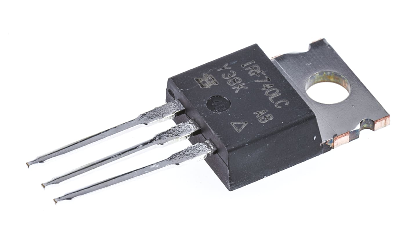
Vishay IRF740LC Type N-Channel Power MOSFET, 10 A, 400 V Enhancement, 3-Pin TO-220AB IRF740LCPBF
- RS 제품 번호:
- 536-5992
- Distrelec 제품 번호:
- 171-15-850
- 제조사 부품 번호:
- IRF740LCPBF
- 제조업체:
- Vishay

본 이미지는 참조용이오니 재확인이 필요하시면 문의해주세요.
대량 구매 할인 기용 가능
View bulk pricing optionsSubtotal (1 unit)*
₩4,520.00
재고있음
- 추가로 2026년 7월 20일 부터 19 개 단위 배송
- 추가로 2026년 7월 27일 부터 2,476 개 단위 배송
더 자세한 내용이 필요하신가요? 필요한 수량을 입력하고 '배송일 확인'을 클릭하면 더 많은 재고 및 배송 세부정보를 확인하실 수 있습니다.
수량 | 한팩당 |
|---|---|
| 1 - 12 | ₩4,520.00 |
| 13 - 24 | ₩4,440.00 |
| 25 + | ₩4,320.00 |
* 참고 가격: 실제 구매가격과 다를 수 있습니다
- RS 제품 번호:
- 536-5992
- Distrelec 제품 번호:
- 171-15-850
- 제조사 부품 번호:
- IRF740LCPBF
- 제조업체:
- Vishay
사양
참조 문서
제정법과 컴플라이언스
제품 세부 사항
제품 정보를 선택해 유사 제품을 찾기
모두 선택 | 제품 정보 | 값 |
|---|---|---|
| 브랜드 | Vishay | |
| Product Type | Power MOSFET | |
| Channel Type | Type N | |
| Maximum Continuous Drain Current Id | 10A | |
| Maximum Drain Source Voltage Vds | 400V | |
| Package Type | TO-220AB | |
| Series | IRF740LC | |
| Mount Type | Through Hole | |
| Pin Count | 3 | |
| Maximum Drain Source Resistance Rds | 550mΩ | |
| Channel Mode | Enhancement | |
| Minimum Operating Temperature | -55°C | |
| Forward Voltage Vf | 2V | |
| Maximum Power Dissipation Pd | 125W | |
| Typical Gate Charge Qg @ Vgs | 39nC | |
| Maximum Gate Source Voltage Vgs | 30V | |
| Maximum Operating Temperature | 150°C | |
| Length | 10.41mm | |
| Standards/Approvals | RoHS | |
| Width | 4.7mm | |
| Height | 9.01mm | |
| Automotive Standard | No | |
| 모두 선택 | ||
|---|---|---|
브랜드 Vishay | ||
Product Type Power MOSFET | ||
Channel Type Type N | ||
Maximum Continuous Drain Current Id 10A | ||
Maximum Drain Source Voltage Vds 400V | ||
Package Type TO-220AB | ||
Series IRF740LC | ||
Mount Type Through Hole | ||
Pin Count 3 | ||
Maximum Drain Source Resistance Rds 550mΩ | ||
Channel Mode Enhancement | ||
Minimum Operating Temperature -55°C | ||
Forward Voltage Vf 2V | ||
Maximum Power Dissipation Pd 125W | ||
Typical Gate Charge Qg @ Vgs 39nC | ||
Maximum Gate Source Voltage Vgs 30V | ||
Maximum Operating Temperature 150°C | ||
Length 10.41mm | ||
Standards/Approvals RoHS | ||
Width 4.7mm | ||
Height 9.01mm | ||
Automotive Standard No | ||
Vishay IRF740LC Series Power MOSFET, 400V Drain Source Voltage, 10A Continuous Drain Current - IRF740LCPBF
This power MOSFET is a high-voltage switching device designed for industrial and electronic control environments. It operates as an N-channel enhancement-mode transistor capable of handling elevated drain-to-source voltages and moderate continuous currents, making it suitable for power conversion and switch-mode circuits in automation and electrical systems. The device is supplied in a through-hole TO-220AB package for straightforward mounting and thermal interfacing.
Features and Benefits:
• 400V maximum drain voltage delivers high-voltage switching capability • 10A continuous drain current supports moderate load currents • 125W maximum power dissipation enables higher thermal throughput • 550mΩ Rds(on) minimises conduction losses under load • 39nC typical gate charge allows predictable switching energy • ±30V gate tolerance protects gate from excessive drive excursions
Applications
• Suitable for switch-mode power supplies in industrial controllers • Ideal for inverter stages in motor drive units • Used for high-voltage relay and contactor replacement circuits • Can be used for lighting ballast and power factor correction modules • Used with discrete driver stages in prototyping and repair
What temperature range can it operate within?
It functions across a wide thermal span from -55°C up to 150°C, permitting use in harsh ambient conditions and elevated junction scenarios.
How is the component mounted and cooled in typical assemblies?
It uses a through-hole TO-220AB format that allows screw or clip mounting to heatsinks for enhanced thermal dissipation and mechanical stability.
What gate-drive considerations should be observed?
The gate may be driven up to ±30V
designers should limit Peak drive pulses and account for the 39nC gate charge to size driver current and switching transition times.
Are there approvals or restrictions noted for regulatory compliance?
The device meets RoHS requirements, indicating it adheres to restrictions on certain hazardous substances for electronic components.
관련된 링크들
- Vishay IRF740LC Type N-Channel MOSFET, 10 A, 400 V Enhancement, 3-Pin TO-220
- Vishay IRF840LC Type N-Channel MOSFET, 8 A, 500 V Enhancement, 3-Pin TO-220 IRF840LCPBF
- Vishay IRF840LC Type N-Channel MOSFET, 8 A, 500 V Enhancement, 3-Pin TO-220
- Vishay IRF740A Type N-Channel MOSFET, 10 A, 400 V Enhancement, 3-Pin TO-220 IRF740APBF
- Vishay IRF740A Type N-Channel MOSFET, 10 A, 400 V Enhancement, 3-Pin TO-220
- Vishay IRF Type N-Channel MOSFET, 10 A, 400 V Enhancement, 3-Pin TO-220 IRF740PBF
- Vishay IRF740S Type N-Channel MOSFET, 10 A, 400 V Enhancement, 3-Pin TO-263 IRF740SPBF
- Vishay IRF Type N-Channel MOSFET, 10 A, 400 V Enhancement, 3-Pin TO-220