Vishay SIHK Type N-Channel MOSFET, 21 A, 650 V Enhancement, 8-Pin PowerPAK 10 x 12 SIHK125N60EF-T1GE3
- RS 제품 번호:
- 268-8312
- 제조사 부품 번호:
- SIHK125N60EF-T1GE3
- 제조업체:
- Vishay

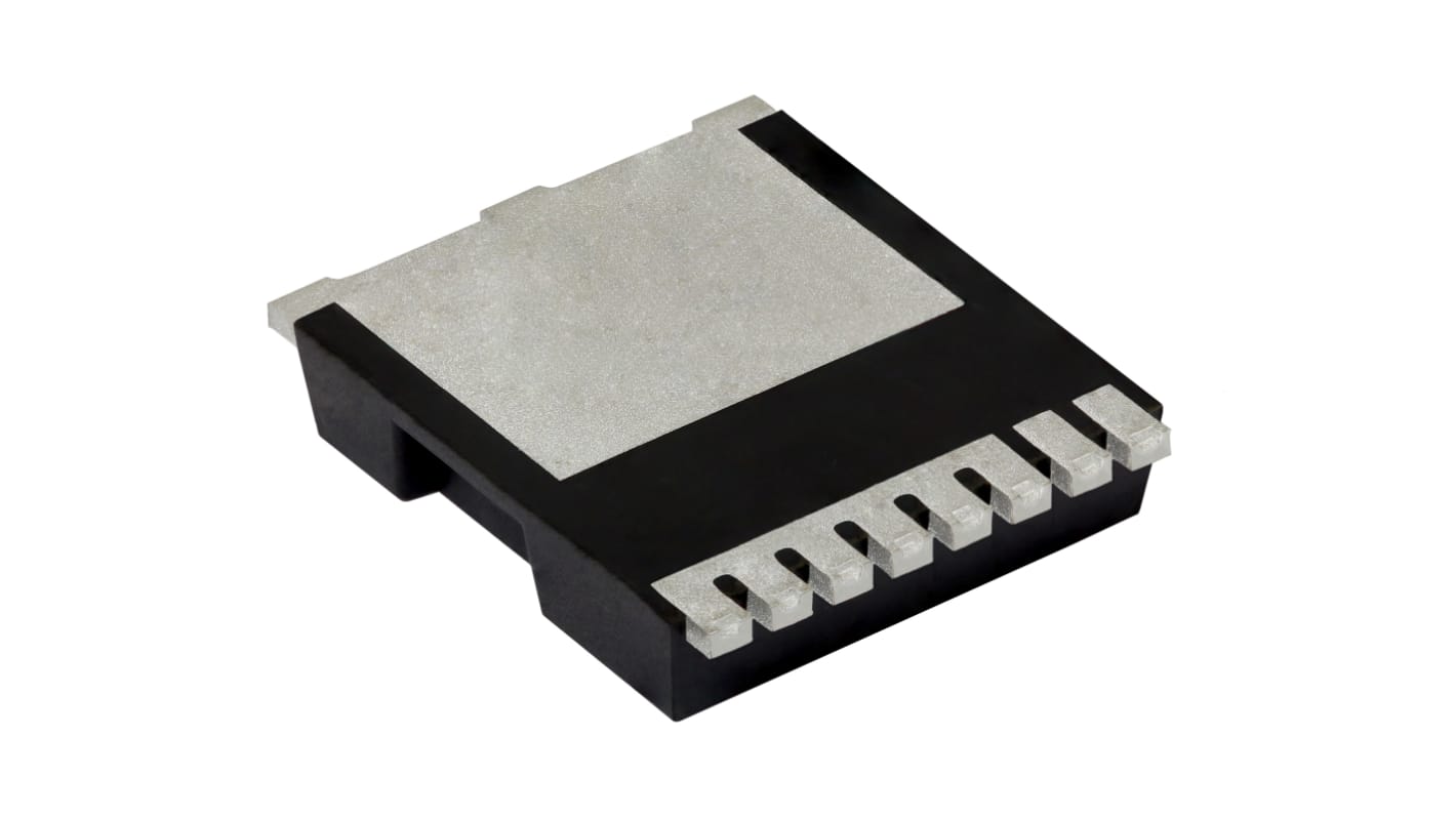
본 이미지는 참조용이오니 재확인이 필요하시면 문의해주세요.
Subtotal (1 reel of 2000 units)*
₩9,788,000.00
일시적 품절
- 2027년 2월 02일 부터 배송
더 자세한 내용이 필요하신가요? 필요한 수량을 입력하고 '배송일 확인'을 클릭하면 더 많은 재고 및 배송 세부정보를 확인하실 수 있습니다.
수량 | 한팩당 | 릴당* |
|---|---|---|
| 2000 + | ₩4,894.00 | ₩9,788,400.00 |
* 참고 가격: 실제 구매가격과 다를 수 있습니다
- RS 제품 번호:
- 268-8312
- 제조사 부품 번호:
- SIHK125N60EF-T1GE3
- 제조업체:
- Vishay
사양
참조 문서
제정법과 컴플라이언스
제품 세부 사항
제품 정보를 선택해 유사 제품을 찾기
모두 선택 | 제품 정보 | 값 |
|---|---|---|
| 브랜드 | Vishay | |
| Product Type | MOSFET | |
| Channel Type | Type N | |
| Maximum Continuous Drain Current Id | 21A | |
| Maximum Drain Source Voltage Vds | 650V | |
| Package Type | PowerPAK 10 x 12 | |
| Series | SIHK | |
| Mount Type | PCB | |
| Pin Count | 8 | |
| Maximum Drain Source Resistance Rds | 0.125Ω | |
| Channel Mode | Enhancement | |
| Maximum Power Dissipation Pd | 132W | |
| Minimum Operating Temperature | -55°C | |
| Typical Gate Charge Qg @ Vgs | 45nC | |
| Forward Voltage Vf | 1.2V | |
| Maximum Operating Temperature | 150°C | |
| Standards/Approvals | RoHS | |
| Length | 9.9mm | |
| Automotive Standard | No | |
| 모두 선택 | ||
|---|---|---|
브랜드 Vishay | ||
Product Type MOSFET | ||
Channel Type Type N | ||
Maximum Continuous Drain Current Id 21A | ||
Maximum Drain Source Voltage Vds 650V | ||
Package Type PowerPAK 10 x 12 | ||
Series SIHK | ||
Mount Type PCB | ||
Pin Count 8 | ||
Maximum Drain Source Resistance Rds 0.125Ω | ||
Channel Mode Enhancement | ||
Maximum Power Dissipation Pd 132W | ||
Minimum Operating Temperature -55°C | ||
Typical Gate Charge Qg @ Vgs 45nC | ||
Forward Voltage Vf 1.2V | ||
Maximum Operating Temperature 150°C | ||
Standards/Approvals RoHS | ||
Length 9.9mm | ||
Automotive Standard No | ||
- COO (Country of Origin):
- CN
Vishay SIHK Series MOSFET, 650V Maximum Drain Source Voltage, 21A Maximum Continuous Drain Current - SIHK125N60EF-T1GE3
This MOSFET is a high-voltage N-channel switching transistor designed for power conversion and control on printed circuit boards. It suits demanding electrical and electronic systems where elevated drain-to-source voltage handling and substantial current capability are required. The device is supplied in a Compact PowerPAK 10x12 package for PCB mounting and is intended for applications that operate across a wide temperature range.
Features and Benefits:
• 650V drain-to-source rating enables high-voltage switching
• 21A continuous drain current supports heavy load duty
• 0.125Ω Rds(on) reduces conduction losses at operating current
• 45nC typical gate charge allows efficient gate-drive management
• 132W power dissipation permits substantial thermal loading
• 21A continuous drain current supports heavy load duty
• 0.125Ω Rds(on) reduces conduction losses at operating current
• 45nC typical gate charge allows efficient gate-drive management
• 132W power dissipation permits substantial thermal loading
Applications
• Suitable for industrial motor drive inverter stages
• Ideal for high-voltage power supplies in automation systems
• Used for switch-mode power conversion in electrical equipment
• Can be used for medium-power traction and conversion modules
• Ideal for high-voltage power supplies in automation systems
• Used for switch-mode power conversion in electrical equipment
• Can be used for medium-power traction and conversion modules
What voltage stress can it withstand in switching circuits?
It can handle up to 650V between drain and source, making it appropriate for high-voltage topologies.
How does gate-charge affect drive design?
A typical gate charge of 45nC informs gate-driver current and switching-loss calculations during transition events.
What thermal extremes can it operate within?
Operational limits span from -55°C at the low end to 150°C at the high end for junction temperatures.
How many pins and what mounting style does it use?
It is an 8-pin device intended for PCB mounting in a PowerPAK 10x12 footprint.
What is the maximum permissible gate voltage?
The gate may be driven up to 30V relative to source without exceeding its gate‑source rating.
관련된 링크들
- Vishay SIHK Type N-Channel MOSFET, 21 A, 650 V Enhancement, 8-Pin PowerPAK 10 x 12 SIHK125N60EF-T1GE3
- Vishay SIHK Type N-Channel MOSFET, 47 A, 650 V Enhancement, 8-Pin PowerPAK 10 x 12 SIHK045N60EF-T1GE3
- Vishay SIHK Type N-Channel MOSFET, 16 A, 650 V Enhancement, 8-Pin PowerPAK 10 x 12 SIHK185N60EF-T1GE3
- Vishay SIHK Type N-Channel MOSFET, 30 A, 650 V Enhancement, 8-Pin PowerPAK 10 x 12 SIHK085N60EF-T1GE3
- Vishay SIHK Type N-Channel MOSFET, 24 A, 650 V Enhancement, 8-Pin PowerPAK 10 x 12 SIHK105N60EF-T1GE3
- Vishay SIHK Type N-Channel MOSFET, 18 A, 600 V Enhancement, 8-Pin PowerPAK 10 x 12 SIHK155N60EF-T1GE3
- Vishay SIHK Type N-Channel MOSFET, 24 A, 650 V Enhancement, 8-Pin PowerPAK 10 x 12 SIHK105N60E-T1-GE3
- Vishay Type N-Channel MOSFET & Diode, 33 A, 650 V Depletion, 8-Pin PowerPAK 10 x 12 SIHK075N60EF-T1GE3